Disclaimer:
- This Article on iNNovationMerge blog is for demonstration purpose.
- Each demonstration presents risk and hazards that must be fully understood before attempting
- It should be performed only by trained professionals
- iNNovationMerge is not responsible for any loss or damage whatsoever caused
- Before attempting understand the Experiment completely or Contact iNNovationMerge for any clarification to get started.
For Feedbacks | Enquiries | Questions | Comments - Contact us @ innovationmerge@gmail.com
What?
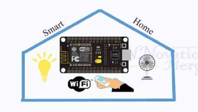
- Home Automation are buzzing words happening in the field of Internet of Things(IoT) from past years.
- IoT based Home automation is controlling Home appliances(Fan, LED Light, Fridge etc.,) from following ways:
- IR Remote
- RF based
- Bluetooth
- Mobile Wifi through android apps
- Voice assistants
- There are different ways for the implementation of IoT based Home automation.
- This article explains how can we make use of NodeMcu for controlling a Home Lamp using Mobile Browser over Wifi.
Why?
- Save electricity and in turn save money
- Better level of comfort
- Peace of mind
- Manage all home devices at one place
- Remote control of Home functions
- Increased energy efficiency by automation
How?
Hardware’s Required:
- ESP8266 CP2102 NodeMCU
- Micro USB cable
- 5V 1A DC Power Supply
- Bread Board
- 5V 10A 1 CHANNEL RELAY
- BC547 NPN Transitor
- 220 ohm Resistor
- Jumper wires
Software’s Required:
- Arduino IDE
- Add ESP8266 in Boards>boards manager in Arduino IDE from Tools menu
Network Requirements
- Internet to download packages
Implementation
Block Diagram
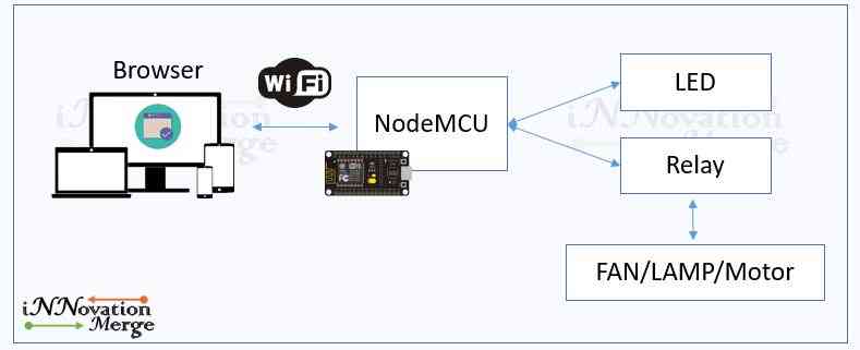
Test NodeMCU with Arduino IDE - Blinking LED
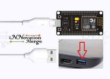
Connect NodeMCU to Laptop using Micro usb cable
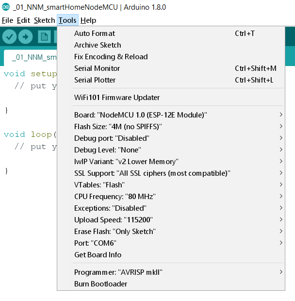
Open Arduino IDE, File -> New -> save as NNM_smartHome and configure like below
Upload below code to Blink the on board LED of NodeMCU
/*
Author : iNNovationMerge
*/


void setup()
{
  pinMode(D0, OUTPUT);      //Built IN LED
}

void loop()
{
  digitalWrite(D0, HIGH);   // Turn on the LED
  delay(1000);              // Wait for one second
  digitalWrite(D0, LOW);    // Turn off the LED
  delay(1000);              // Wait for one second
}- Below Image shows the expected output. Make sure you test this before going to next step.
Lets do the same LED ON and OFF trough mobile over wifi
- Since NodeMCU has Builtin ESP8266 Module , we can configure it as a Wifi Hotspot hence mobiles can connect and control NodeMCU GPIO pins through Browser
- Below code enables NodeMCU as WIFI Hotspot with SSID “iNNovationMerge”, password “123456789” and generates a URL for Browser.
/*
Author : iNNovationMerge
*/

#include <ESP8266WiFi.h>
#include <WiFiClient.h>
#include <ESP8266WebServer.h>

// Replace with your network credentials
const char* ssid = "iNNovationMerge";
const char* password = "123456789";

ESP8266WebServer server(8082);   //instantiate server at port 8082 (http port)

String page = "";
int FANPin = D0;

void setup(void){
//the HTML of the web page
page = "<h1>iNNovationMerge <br> Home Automation using IoT</h1><p>FAN:<a href=\"FANOn\"><button>ON</button></a><a href=\"FANOff\"><button>OFF</button></a></p>";
//make the LED pin output and initially turned off
pinMode(FANPin, OUTPUT);
digitalWrite(FANPin, LOW);
delay(1000);
Serial.begin(115200);

WiFi.softAP(ssid, password); //begin WiFi access point
Serial.println("");;
Serial.print("Connected to ");
Serial.println(ssid);
Serial.print("IP address: ");
Serial.println(WiFi.softAPIP());

//Render Page with buttons once the URL is given
server.on("/", [](){
  server.send(200, "text/html", page);
});.

//Url to turn ON LED - Given as href to ON button
server.on("/FANOn", [](){
server.send(200, "text/html", page);
digitalWrite(FANPin, LOW);
delay(1000);
});

//Url to turn OFF LED - Given as href to OFF button
server.on("/FANOff", [](){
  server.send(200, "text/html", page);
  digitalWrite(FANPin, HIGH);
  delay(1000);
});

//Start the server
server.begin();
Serial.println("Web server started!");
}

void loop(void){
server.handleClient();
}
Upload the above code from Arduino IDE to NodeMCU.
Open serial monitor and get the IP
Search for wifi “iNNovationMerge” in Mobile
Provide password as “123456789”
once it is connected, Open any Browser(Google Chrome)
Provide the IP generated in Serial Monitor (http://192.168.4.1:8082)
The Expected output should be as below
Now we can take advantage of GPIO D0 of NodeMCU to control Home appliances similar to LED.
Since all home appliances run from 230V AC, NodeMCU can’t drive it from its DC output, hence we will need two intermediary components to make this happen
The two components are
- BC547 NPN Transitor - To drive Relay from GPIO
- 5V 10A 1 CHANNEL RELAY - To connect AC Devices from DC input
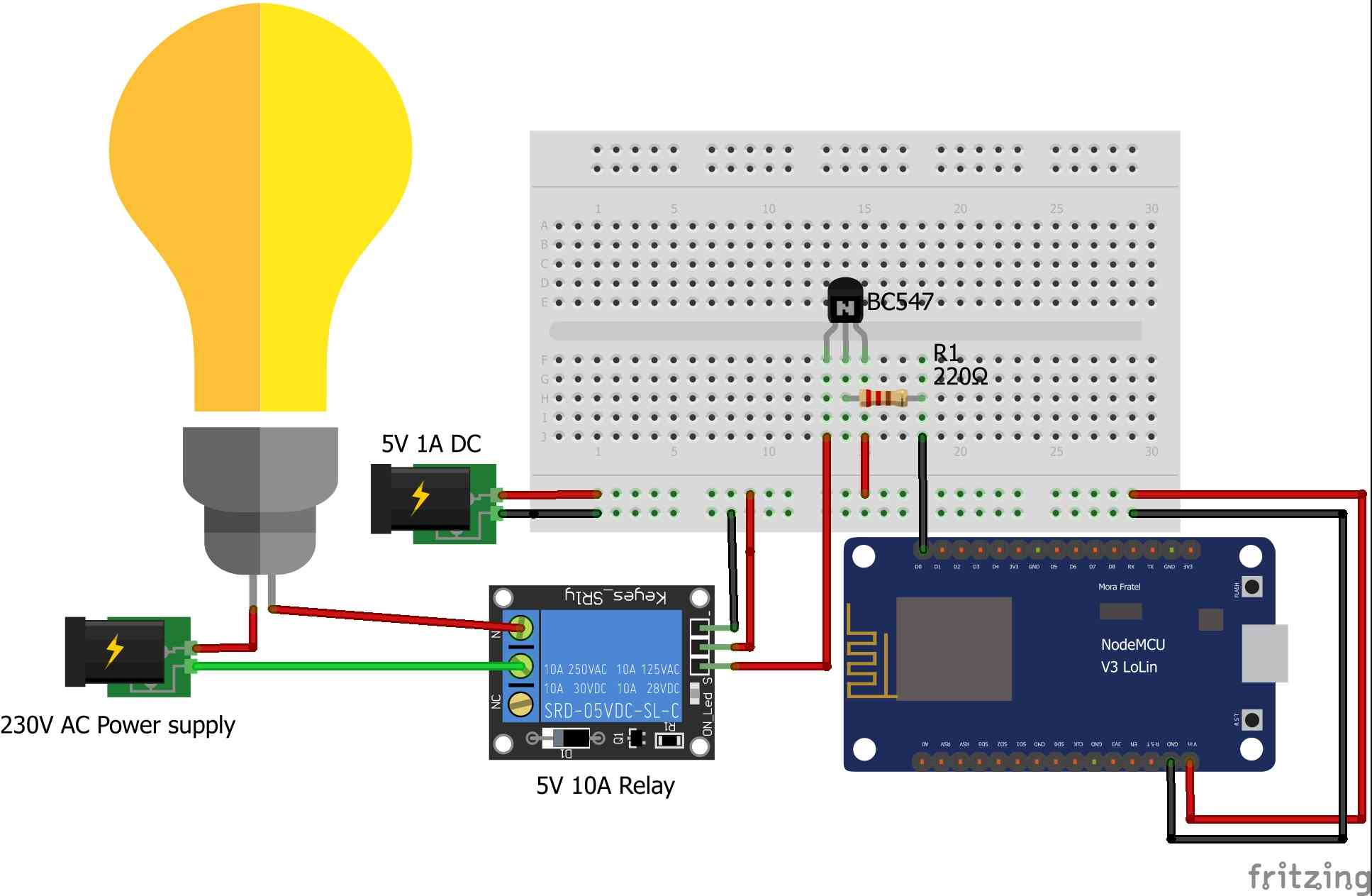
Connect the circuit as below
The Fritzing circuit shows a LAMP connected via Relay
Instead of LED now the GPIO Pin D0 sends the signal to base of Transistor BC547
On signal, Transistor acts as closed switch between emitter and collector hence the current flows to Relay signal pin
On signal on Relay pin, Relay connects Pin Common(C) to Normally open(NO) from Normally closed(NC) and Lamps turn ON
Now in the place of LAMP you can have any 230V AC Home appliances and control over mobile phone
Great, iNNovationMerge hope that you have understood how to make Home Devices smart, which makes Home as Smart Home